Showing posts with label nRF24l01. Show all posts

Saturday, 23 April 2016

Bearstrike update: PCBs

Sorry have been neglecting this blog and posting projects to Bearocratic facebook directly. 
Time for another long overdue update. 

Tagger boards (Gun board). 
The current tagger board is stable, some improvements over the past generations and issues resolved. +5volt step up circuit for better IR range when running off a single cell lipo. 
+USB charging onboard. 
+New formfactor 
+More compact design for more compact taggers. 
+There also has been an overhaul of the user interface to not overwhelm players with too much information. heap of code changes to makes the This version had a issues with connectors covering some of the pin/connector labeling (now fixed)
 No automatic alt text available.No automatic alt text available.


Nade. 
Not much has changed here for a few months, still needs a case but is much more compact than previous generation. still wireless and can be shot. 
Has USB charging onboard. No automatic alt text available.


Headsets. 
Still wireless and still small.
Current version is has USB charging onboard. 
Now instead of two TSOP34856 on the front of the headsensor there is the newer and improved TSOP75356W IR receivers as well as the addition of extra sensors for the side of player’s heads for improved hit detection from all angles. As the headsensor is now much flatter the case design will be much simpler. 
Image may contain: indoorNo automatic alt text available.Image may contain: indoor


LED board 
This board is what is mounted in the tagger behind the lens, this version uses SMD LEDs which allow the muzzle flash to be much more closely grouped with the IR beam. The IR LED is also a OSRAM SFH 4545 that provides better beam angle and spread over the common Vishay TSAL6100. 
The board also has a jumper and optional resistor pads for if you wanted to use this board in taggers using other systems. Image may contain: indoorImage may contain: 3 people


Universal IR Targets. 
These are designed to be low cost simple IR lasertag targets that should work with most systems. The target is semi dumb in the terms that it does not decode the IR data packet, it reacts based off if it received an IR data packets size bigger than the minimum size of most Lasertag systems or even your TV remote while filtering out most interference sources. 
When hit the target flashed, beeps and vibrates so if you attach some to yourself you can tell which direction you were shot from (this overcomes one of the shortcomings that Lasertag has when compared with airsoft or other systems that use projectiles) 

The Arduino source code is free and can be accessed from 
https://bitbucket.org/grobschmit/basic-ir-target/overview Kits will be available from the web store soon which will contain everything you need to assemble one. The board is designed to be as simple as possible with the lowest number of parts and easy to solder. 
The board also has the future option of i2c for if you wanted to create a network of i2c connected sensors or connect the sensors via i2c to other devices.

No automatic alt text available.No automatic alt text available.

Wednesday, 20 January 2016

Turtle watches

Turtle watches
No automatic alt text available.
Something I have been building in my free time over Xmas for some friends. Some wireless smart watches that can be used to help find friends and communicate at festivals and other locations outside of mobile range or places too loud to use radios. 


They create their own wireless mesh network so no need for anything more than just a few of them, also has a beeper and vibration motor so they can vibrate and beep when you come into range of someone you have not seen for a while

And because I like a challenge all coded on an 8bit processor with <30KB flash and 2KB ram (and still have room to grow). This allows me to get 48hrs battery life but also has USB charging without using and advanced power optimization in code (like sleep or synchronized time slotted wireless).

No automatic alt text available.No automatic alt text available.


Decided to change the form factor to a more candy bar shape as would be much more durable than a watchNo automatic alt text available.No automatic alt text available.


No automatic alt text available.
Prototype/relay node. These guys are much bigger but have proven to have a range of over a km from 

basestation

Text messaging
Unlike messaging on most devices the watches work on a word list (text fragment) system.
This means that most sentences can be formed using the following structure:
[Who/Name]  & [Action]  & [Location/Item] & [State/Extra]
This means using predefined text fragment system you can create a messages like
"Robert" "bring" "snacks" "please"
or
"Everyone" "meet at" "camp" "1hr"


Having word lists allows a user to generate a message by selecting the text fragment they want from the from the word list using the arrow keys. This also allows messages to be transmitted as a single 4byte payload and message storage to be just as small. 


Radio
The original hardware design was to have it as a dual radio device utilizing both a nRF24L01+ 2.4Ghz and a SI4432 433Mhz radio and the network stack designed to be able to support this as well as radio bridging and basic meshing but with testing I found the SI4432 radios suffered from bad packet loss issues and performed worse than the nRF24L01+ so it was dropped from the final design.

For the next design I have some LoRa radio modules that I am going to use. I will still use the nRF24L01+ for proximity detection but the ESP32 does look to have a many features like WiFi and Bluetooth that could also be used as well as having a much more powerful processor for the same power cost.   


For future versions I am planning on going to a star network topology, This should improve message delivery as a single gateway in the centre of the network can receive, buffer and deliver the message for users that are out of range. This will also allow me to implement a wireless synchronized time slotted protocol so I can reduce the device power consumption when idle by sleeping the radio and processor to increase the battery life from days to months.


Thursday, 4 June 2015

Bearstrike ESP8266 nRF24L01+ node hubs

Again overdue for an update. 

ESP-HUB

No automatic alt text available.

Here is the latest piece of hardware. 
This board is the latest Hub board, The purpose of this board is to bridge the low powered wireless used by other devices like headsets and taggers to standard 802.11BGN to connect to a cloud hosted game server. 
It also comes with a 1000mAh Lithium ion battery as well as onboard USB charging. 
The processor has also been given a big upgrade over the last one now that it uses the ESP8266 which is a 32bit processor as opposed to the 8bit processor commonly found in Arduinos. 
Currently it supports connecting to existing networks as well as creating it's own wireless network simultaneously so opens up the possibility of phone apps.

Sunday, 15 March 2015

Bearstrike update: Admin boxes, taggers


Admin/util/support boxes.I think this one might be too small now. With its own custom board now with buttons and screen mounted to the board directly things are a lot more compressed now. This could also be used to make a mini pistol tagger with the addition of a lens and a few other parts.
No automatic alt text available.


Tagger case.
The case for the tagger is progressing nicely, most work now is the mounting internals for the electronics.
No automatic alt text available.

Wednesday, 4 June 2014

Bearstrike boards have arrived!

Bearstrike boards have arrived!
No automatic alt text available.
I think I need a bigger table.

It is a bit scary when you look at that pile and think that is 90 players/Zombies & 90 taggers and that number does not include already staged units.
I would so love to round up 110+ players to test out all the prototypes at the same time, would make for some epic gameplay chaos.

Now to start QA'ing and updating all the boards.


Monday, 28 October 2013

RFnode PlayerZ update2

Much has changed since my last update.I now have Zombies and Taggers working and the features list is growing by the day. Even have IFF working.
For more realtime updates check out the photos here 

https://www.facebook.com/BearocraticDesigns

Thursday, 19 September 2013

RFnode PlayerZ update

More progress.

I picked up some Playstation Sharpshooter controllers and converted them with some of the old parts I had. The units are using the older RFnodeB1 board which was not designed for this but still works well. I am due to receive my PlayerZ boards in about 2 weeks and enough parts to make at least 10 zombies(with sound modules) 


I now have a total of 5 working taggers. The Sony Sharpshoot case works well as it has 8 buttons and plenty of space (and is cheap). Currently I have all buttons connected and working but not all assigned to functions yet.


Head sensor is also working using the RFnodeB1 board.


The head unit runs the full version of my PlayerZ code so is the only piece of hardware you need to play (but you might want something to shoot with too). The final version will have more IR LEDs on the front for doing Zombie damage, currently I have just one for testing and using it combined with wireless for Zombie damage.

I am also waiting for the sound modules and speakers so they are missing from the above. I have coded using both a sound module(WTV020) that plays WAV files from the microSD card as well as using a PC speaker style buzzer.

I have also started a Facebook page for my projects, come like me.
https://www.facebook.com/pages/Bearocratic-Designs/229392603876276

Tuesday, 10 September 2013

RFnode PlayerZ (MilesTag based LaserTag)

A few months ago I was introduced to Laser skirmish and I am not talking about the little kids game or walking around with a flashing vest and a sci-fi pistol that has a range of a few meters but taggers of a realistic look/weight/range and sound(Tech Assault). Since then I became a little hooked and in wanting to bring more to the game I started working on a new project. With prototypes on my desk and purpose build boards designed by me on there way I can hardly contain my excitement.

Overview

The RFnode playerZ board is an Arduino based board designed for laser tag. The software is based off the Miles Tag protocol version 1 so is compatible with other systems based that are also using this protocol.
Each board contains a radio that is used to realtime scoring, proximity functions, wireless configuring and node grouping (a number of nodes can make up a player).
The board is designed to be ether a Zombie headset to be worn by a player or as the internals of the Laser tagger.

Features

·         Arduino core (powered by an ATmega328)
·         Sound support (uses a WTV020 sound module with support of upto 512 different sound files stored on a microSD card)
·         Radio support (uses the nRF24l01+ radios with signal range upto 1km*)
·         Programmable radio output: radio can be set to only send short range signals that are only received by other nodes within a few meters.
·         Low cost (our target cost is that you are up and playing for less than $100)
·         1Wire/iButton support (for ingame pickups)
·         i2c support
·         TTL UART support (used for debugging and supports commands)
·         6 button input (more can be added)
·         56Khz IR emission and reception (depending upon lens setup has a range of over 200m)
·         Lithium battery with micro USB charger built in.

Zombie headset mode

Each headset has 2 IR leds for emitting short range Zombie damage from the Zombies head to any other player within range. Zombie damage is also transmitted via low powered RF to other players within 2-3 meters of the zombies.
Zombies have IR hit sensors positioned on the front and back of the head.

Tagger mode

The board (node) can also be used as the internals of a player’s tagger. The player can choose to have a head sensor wired to the tagger (Currently how most laser tag is played) or the node can be grouped to a player wearing a Zombie headset.
Can be added to Nerf guns in a none destructive way (clips to Nerf rails).

Node Player grouping

The MilesTag protocol only supports 256 unique players (8 teams of 64 players). For us to be compatible with MilesTag and compatible systems this affects us too but it only affects the IR data, our radio code supports 65025 unique nodes.
We have designed it so any number of nodes can be assigned to a player, this means that if we wanted too we can assign 1000 taggers to one player or 1000 headsets to one player. If you want to have multiple taggers per game we support it

Radio Proximity

We have radios with programmable output so we can control the range to add proximity based game elements. We use this to do Zombie damage if you are within 2-3 meters of a zombie but we use this also for a number of other features like Capture points, if you are with an area with a capture node you can capture it. We also support the sending and receiving of powerups from nodes, if you want to be a medic you can but watch out for the  

In Game PickUps

As the boards support iButtons we can use these for in game pickups. This could be used for items like weapon upgrades, health packs or game objectives hidden around the playing field. We also support wireless Pickups too.  

Backend Server Support

Our nodes like to talk to our server and our server can talk back. Not only do we use this for real time scoring but we can also use this to send you power ups mid game. Don’t like your taggers gun profile? Just use your smartphone or a connected device to select a new one and we will update your tagger with a new one. Want to know where you team is? We can tell you which nodes they are near on a map. Want to know your stats mid game? we can give you  more data then you poke sharp stick at.  


One of the new designs compared with RFnodeB1 board used in current prototypes.


My Modded Nerf gun with attached board and lens. Nerf gun is dual purpose can be used for lasertag and can still fire Nerf.

Thursday, 11 October 2012

A smarter garden Gnome

A smarter garden Gnome.


Still a work in progress but meet one of my garden gnomes. 

I still need to print him a better case to mount the soil moisture pins better and make him more presentable in general.  


At his heart he is powered by one of my RFnodes so he is wireless and has an array of sensors that he reports on back to the network. He currently reports back the light levels, soil moisture, temperature, humidity and having a RGB led that make him glow any color I can have him signal the plants status or as being network I can use the RGB led to make him (and his friends) signal anything the network want him to.

I have some small PIR motion sensors I also want to mount as his nose and print a case that can house the bigger batteries required by the RGB led.


Saturday, 22 September 2012

Wireless mesh-able RGB lights and a ATMEGA88


I thought I might test out using the Atmega88p-20au instead of the Atmega168 as a processor for my RFnode. The Atmega88 is a cheaper version of the Atmega168 with only half the flash. 

I had tried using a Atmega8 before but found it did not run too stable at 3.3volts which I need to do to support USB. The Atmega8 datasheet said it  needs 4.5 - 5.5 volts but I was going to give it a go anyway, It did work but I found that about 1 in 5 times I when flashing it I would get an error and would have to retry.


Reading the datasheet the Atmega88 is identical to the Atmega168 with the main differences being just the amount of flash/ram. So hardware wise I did not need to make any changes except the IC but from a software side I did have to change my code a fair amount to get it down to 6KB. The Atmega does have 8KB of flash but I am using 2KB of that for the bootloader.  

After removing all the sleep/watchdog functions and cutting back the meshing support I was able to get my code to less then 6KB and still be left with a wireless mesh-able RGB light with a just enough code space left to added a few basic sensors. 

This version of the board I made it easier to add a STA301A so it would be easy for me use this board to drive brighter and more power hungry lights or devices around the home and have them all wirelessly controllable from my tablet/phone. 

Monday, 20 August 2012

RFnode 1.3

I received some of the PCBs for the new version of my RFnode so I spent a little time today soldering it all together and testing it out. 

This version of the board has following features.

+RGB led (on PWM pins D5, D6, D10) now can make any color.
+CR2032 lithium coin battery powered or USB powered
+Power selector switch to select between USB power and battery(CR2032)
+USnooBie compatible (http://www.frank-zhao.com/usnoobie/
+Programmable via mini USB port (USBISP) and supports the Arduino IDE (USnooBie bootloader)
+nRF24L01+ 2.4Ghz radio transceiver 
+3.3 Volts @ 12Mhz (onboard voltage regulator)
+Breadboard friendly if you add the header (even mini breadboard)
+Only 46x24mm board size 
+SMD parts (to keep testing my soldering skills)


All assembled with radio and breadboard header, ready to go 


With CR2032 battery 

In mini breadboard, without radio attached

Friday, 6 July 2012

RFnodes v1.0 + Bluetooth + Solarbattery

RFnode with Bluetooth and solar battery attached. 
Just a quick post to show a Bluetooth module connected and powered by a solar battery.
What you can't see is that it is connected to my tablet via Bluetooth (only a serial console over Bluetooth)

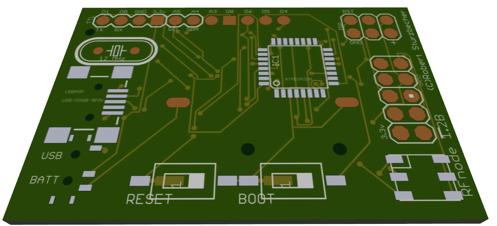
RFnode 1.2b PCB update


RFnode PCB version 1.2b almost ready for printing and have made many changes with this version (and a few more to come).

Major changes so far:


  • Added SDcard slot for storage on the under side. This will allow the RFnode to be used as a data logger. The problem with SDcard slot is that takes up a large chunk of PCB space and the SDcard libraries take up a lot of programming space so if using a Atmega168 you need to keep a close eye on your program size.
  • Replace Red&Green LEDs with a RGB LED. This opens up the full spectrum of colors. This also means I loose 3 analog I/Os but gain 2 digital I/Os. This leaves me with -3 Analog I/Os (includes 2 for i2c bus)
    -6 Digital I/Os (Includes 2 for serial and 1 for SDcard if used)
  • Breadboard friendly pin header. Now all of the I/Os are on a single 11pin breadboard friendly header. The boards were going to be just for another project I am working but have decided to open it up a little. So that means making the board more general purpose and Arduino hacker friendly.  
  • Better power consumption. I ended up caving in and adding a switch to select power source. It seemed to be the most simplest and cost effective solution to the power consumption issue I was having with the power regulator.
  • Optional pull up resistor pads added for D6 & D8. Makes it easy to add 1wire digital sensors like the DHT11 & DHT22 temperature and humidity sensors.    

Future Changes:
The board still has room to grow so there are some more changes to come.


  • Size. The board has grown a little in this version while I sort out and move features around but is still only approximately 45mm X 35mm. Most of that space is due to connectors and a few parts.
  • Lithium ion support. Looking to add a charge and protection circuitry for Lithium ion battery packs. Looks like a MCP73831T could handle the charging of the battery but now need to source the cut off protection side of things to protect the battery voltage from dropping too low. The problem with this I am running into is cost. It is cheaper to but a phone battery that has this built in then it is to buy the circuit by it's self. Currently I do lithium ion battery protection via software were the software will check the battery voltage then if it is too low will go to sleep (but still consumes a little less then 0.1mAh) 
  • More I/Os. The Radio uses 6 digital I/Os and the RGB LED uses 3 analog I/Os. Then if Using SDcard, serial and i2c bus you only get left with about 4 I/Os so I want to add more I/Os. I know there are chips that allow using the i2c bus to give you an extra few I/Os but I am thinking about something a little more powerful then one of these guys. I am thinking about adding a whole second processor. If I add a second Atmega168/328 I could off load all of the sensor work to the second processor leaving the first processor to handle the communications (USB, Radio, SDcard, RGB LED) then the second processor to handle everything else with almost all of his I/Os (13 digital and 4 Analog).
  • More memory. One of the problems I ran into with creating a meshing protocol with the RFnode beside battery life was lack of memory, routing tables take a lot of space. I did come up with a few memory tricks like creating a u_int8[256] array using the index as the remote RFnode ID then the value being where to address the packet so the next node can follow the same process and pass it on. This allowed to have a routing table of less then 256 nodes in 256bytes of memory. With a Atmega168 this is still about 25% of ram of 50% of EEPROM space and does not leave much space for routing data like number of hops and route health but still possible.
    So to fix the memory issue I am thinking about adding a i2c based ram/flash chip. This will also allow data logging without using the SDcard. 

RFnodes v1.1

RFnode PCB v1.1a
This version of the PCB I move some of the pins around to makes the unit more compact. As the boards normally take 3-4 weeks from time of ordering to arriving I ordered these boards before I had received and tested the Version 1.0 PCBs so had many of the same issues  


Assembled board with DHT11 temperature/humidity sensor attached

AMS1117 power consumption work around.
As a workaround to the AMS1117 power consumption issue I tried adding a diode that helped but only helped by dropped by about 70% and introduced a new issue of voltage drop from the voltage regulator dropping the voltage from 3.3 volts to 2.6 volts. USB still works and the board operates fine but not a long term fix.


I am trying to keep the board as user simple as possible so did not want to add switches. I also want to keep the board cost low so didn't want start adding item that would raise the cost too much (p-channel mosfets


RFnodes v1.0

RFnode v1.0
Time for a second post. This time with pictures.

These little guys are the Version 1.0 RFnodes I was working on, These were the first version I designed so expected a few issues. It is all part of my self inflicted crash coarse into PCB design and SMD (surface mount). This board is a few weeks old now and I have moved on to better designs since. 

The good
  • They are Arduino based (Atmega328/168) 
  • V-USB bootloader (same as USnooBie) http://www.frank-zhao.com/usnoobie/index.php
  • Runs at 12Mhz @ 3.3volts with onboard voltage regulator (AMS1117 3.3)
  • USB or 3 volt coin cell powered (CR2032) 
  • The PCB is designed by me from the ground up (printed in china)
  • Compatible with the USnooBie (as I own a few of them too and over time have found them easier to work with then many Arduinos)
  • Supports V-USB http://www.obdev.at/products/vusb/index.html
  • Uses nRF24L01+ 2.4Ghz radio 
  • Mostly SMD parts (and all soldered by hand) 
  • Some parts not SMD so I could change the sides if I wanted
  • 4 digital IOs (2 used for serial)
  • 6 Analog IOs (2 used for I2C)
  • 2 LEDS (Red/Green) 
  • ISP Header (only used for loading bootloader or adding another SPI device)
  • Can consume <0.1mAh in sleepmode and about 0.5mAh idle (read below)
     
 The Bad
  • The Radio overhang. This was done on purpose for this version of the board so the antenna is free from interference from the main board. After a bit of testing I decided I did not need to position the radio in such a way. 
  • SMD pad sizes. As I am a little new to SMD parts and their required pad sizes on the PCB some of my pads where too small for the part. Well it was only one part, The main power capacitor which I ended up just soldering to the voltage regulator pins.
  • Silk screen. Not all of the silk screen was printed or was too small or mostly off the edge of the board after cutting.   
  • Power consumption. Board was consuming about 17.5mAh so a CR2032 would only last about 6 hours which is less then the maths that said I should be able to get up to about 5 months. Issue turned out to being the AMS1117 power regulator would still consume about 4mAh if power was connected to it's output. I thought it was only meant to consume power if connected to input only. I also found that the radio was consuming about 13.5mAh when idle in RX mode. So after disconnecting the voltage regulator and powering down the radio when not in use I can the power consumption to less then 0.3mAh and less then 0.1mAh when in sleep mode.     
My finger compared to it's size, all soldered by hand (mostly my off hand)