Showing posts with label PCB. Show all posts

Saturday, 23 April 2016

Bearstrike update: PCBs

Sorry have been neglecting this blog and posting projects to Bearocratic facebook directly. 
Time for another long overdue update. 

Tagger boards (Gun board). 
The current tagger board is stable, some improvements over the past generations and issues resolved. +5volt step up circuit for better IR range when running off a single cell lipo. 
+USB charging onboard. 
+New formfactor 
+More compact design for more compact taggers. 
+There also has been an overhaul of the user interface to not overwhelm players with too much information. heap of code changes to makes the This version had a issues with connectors covering some of the pin/connector labeling (now fixed)
 No automatic alt text available.No automatic alt text available.


Nade. 
Not much has changed here for a few months, still needs a case but is much more compact than previous generation. still wireless and can be shot. 
Has USB charging onboard. No automatic alt text available.


Headsets. 
Still wireless and still small.
Current version is has USB charging onboard. 
Now instead of two TSOP34856 on the front of the headsensor there is the newer and improved TSOP75356W IR receivers as well as the addition of extra sensors for the side of player’s heads for improved hit detection from all angles. As the headsensor is now much flatter the case design will be much simpler. 
Image may contain: indoorNo automatic alt text available.Image may contain: indoor


LED board 
This board is what is mounted in the tagger behind the lens, this version uses SMD LEDs which allow the muzzle flash to be much more closely grouped with the IR beam. The IR LED is also a OSRAM SFH 4545 that provides better beam angle and spread over the common Vishay TSAL6100. 
The board also has a jumper and optional resistor pads for if you wanted to use this board in taggers using other systems. Image may contain: indoorImage may contain: 3 people


Universal IR Targets. 
These are designed to be low cost simple IR lasertag targets that should work with most systems. The target is semi dumb in the terms that it does not decode the IR data packet, it reacts based off if it received an IR data packets size bigger than the minimum size of most Lasertag systems or even your TV remote while filtering out most interference sources. 
When hit the target flashed, beeps and vibrates so if you attach some to yourself you can tell which direction you were shot from (this overcomes one of the shortcomings that Lasertag has when compared with airsoft or other systems that use projectiles) 

The Arduino source code is free and can be accessed from 
https://bitbucket.org/grobschmit/basic-ir-target/overview Kits will be available from the web store soon which will contain everything you need to assemble one. The board is designed to be as simple as possible with the lowest number of parts and easy to solder. 
The board also has the future option of i2c for if you wanted to create a network of i2c connected sensors or connect the sensors via i2c to other devices.

No automatic alt text available.No automatic alt text available.

Thursday, 7 April 2016

One time use USB


One time use USB
I was given a requirement for a single use USB drive that can be used to update the firmware of a single machine then would disable to limit the distribution of the file. The drive should also be not readable on desktop computers.   

Not being being able to find a single use USB drive a manufacturer in China able to offer me drives with SDK I decided I would make it myself


The drive is based around the ATmega32u4 running LUFA, now the USB on the 32u4 is not the fastest but as I only need to deliver a 1MB file it does not need to be the fastest so a 32u4 is one of the simplest processors I could get away with.

The drive will disable once the firmware file has been completely read by the target machine. There is also logic to disable the drive if any other files are read, this means if the drive is connected to a PC or MAC and it tries to read autorun.inf or any thumbnails the drive will instantly disable reading of the drive.

The unit can also act as a Arduino with the right bootloader installed and with a SDcard socket onboard could be useful as generic USB powered datalogger.

Thursday, 4 June 2015

Bearstrike ESP8266 nRF24L01+ node hubs

Again overdue for an update. 

ESP-HUB

No automatic alt text available.

Here is the latest piece of hardware. 
This board is the latest Hub board, The purpose of this board is to bridge the low powered wireless used by other devices like headsets and taggers to standard 802.11BGN to connect to a cloud hosted game server. 
It also comes with a 1000mAh Lithium ion battery as well as onboard USB charging. 
The processor has also been given a big upgrade over the last one now that it uses the ESP8266 which is a 32bit processor as opposed to the 8bit processor commonly found in Arduinos. 
Currently it supports connecting to existing networks as well as creating it's own wireless network simultaneously so opens up the possibility of phone apps.

Monday, 22 October 2012

Projects of interest

Hi Peoples,

I have 3 projects that I am starting on but want to gauge interest levels. 
All 3 projects will be the basses for other bigger projects.
Projects 2 & 3 are the easiest as I have already done them before in concept.

Project 1 has the most potential in my mind but requires me to work with an overseas vendor with less control over the project. 


Project 1, Arduino Wifi access point shield/Cloud connected Arduino.
Backgound:
Currently you can get Wifi shields and network shields for Arduinos but the Arduino lacks the resources to use the full potential of the these, this includes full featured web pages and full network stack. 

In looking for ways to bridge my RFnodes to the internet I have played around with openWRT and using Arduino to control pocket sized Wifi routers. I have come across small Wifi device that can be used as a accesspoint or in client mode, has 1mb of web space and has a TTL UART for connecting serial devices like an Arduino. The serial port can be used to pass data back to a web service allowing you to have a cloud connected Arduino project. As it only uses the TTL RX/TX pins you have all you other pins free for you project and only requires you to include code if you want to configure the Wifi shield.
You can create web pages in the shield that would allow you to send data to Arduino project and has support for a camera, so you can even create a wifi controlled pan/tilt camera.
  
Goal: 
Bridge Arduino projects to the internet via Wifi.
Make it easier for internet controlled Arduino projects with web interfaces and support web services/cloud services.

Specs:
802.11BG router with support for AP/STA mode
TTL UART
1MB user space for web pages and scripts


Risks&issues:
Still scoping


Project 2, Arduino with H-bridge and Bluetooth

Backgound:
I am looking to make a small PCB with an Atmega88/168/328 with support for the Arduino IDE. The design will be based around the RFnode but without the radio and a 2 channel H-bridge and TTL Bluetooth UART module in its place.

The board will support 2 bidirectional motors and with Bluetooth can be paired and controlled by almost any smartphone.

So making something like a little robot tank that is controlled by your phone will be an trivial task.

Board will be programmed via USB using the V-USB, This also supports making the board act as a HID keyboard/mouse/...

Goal: 
Create a low cost small Bluetooth Arduino with onboard H-Bridge.
By creating a
standard smartphone compatible Bluetooth robot board we might get some more app developers onboard.

Specs:
+ V-USB Arduino (http://www.obdev.at/products/vusb/index.html)
+ 2 channel H-Bridge with support for 2 motors
+ Bluetooth UART module

Risks&issues:
+ Cost to assemble may make this non-economical unless can get numbers


Project 3, Low cost Atmega88 based Arduino 

Backgound:
There have been a few Attiny boards starting to popup that support the Arduino IDE. These boards use the Attiny instead of the Atmega as they are cheaper but do not have all the features of an Atmega. Not only do they not have as much Ram/Flash/Eprom but are also lacking support for some Arduino functions.

An Atmega88 is compatible with a Atmega168/328 and so the Arduino IDE but almost the same price as the Attiny. It should be possible to create a low cost Adruino clone for less then $5 worth of parts. 


Goal: 
Low cost Atmega88 Arduino board for less then $5

Specs:
+ Atmega88(6k application space)
+ V-USB Arduino (http://www.obdev.at/products/vusb/index.html)


Risks&issues:
+ SMD parts (to hard for most people to solder)
+ Cost to assemble may make this non-economical and more expensive then a full feature Arduino unless can get done in large numbers


Friday, 14 September 2012

Burningman wireless bike lights

Some good friends of mine wanted some bike lights for Burning man this year, but did not want just bike lights. 

RGB wireless bike light

So I created them wireless bike lights that beep and flash like a car alarm arming/disarming. When in the on mode the head light is on and a string of LED will pulse allowing them to see and be seen.


For the electronics I used one of my Arduino based RFnode as a base but to drive the power hungry LEDs I used a STA301A connected to 3 of the PWM pins of the ATmega168. This allowed me to drive 3 strings of LEDs with PWM support. 


I got a little creative and limited by space and time I mounted the STA301A to the RFnode with some hot glue and mounted surface mount resistors directly to the pins of the IC. Most of the wiring was air wiring as I did not have time to get a customer board fabricated.

For the radio instead of using the nRF24l01+ I found some small key finder fobs that can stay powered from a coin cell battery for months so decided to use them as I could get the power consumption down to less then 1mAh when in sleep mode.   


I was in a bit of a rush to get the units finished before Burningman so I don't have any pictures of the hardware jammed back into the bike light casing and the extra wiring of the LEDs yet. I might add that one they get back.

Monday, 20 August 2012

RFnode 1.3

I received some of the PCBs for the new version of my RFnode so I spent a little time today soldering it all together and testing it out. 

This version of the board has following features.

+RGB led (on PWM pins D5, D6, D10) now can make any color.
+CR2032 lithium coin battery powered or USB powered
+Power selector switch to select between USB power and battery(CR2032)
+USnooBie compatible (http://www.frank-zhao.com/usnoobie/
+Programmable via mini USB port (USBISP) and supports the Arduino IDE (USnooBie bootloader)
+nRF24L01+ 2.4Ghz radio transceiver 
+3.3 Volts @ 12Mhz (onboard voltage regulator)
+Breadboard friendly if you add the header (even mini breadboard)
+Only 46x24mm board size 
+SMD parts (to keep testing my soldering skills)


All assembled with radio and breadboard header, ready to go 


With CR2032 battery 

In mini breadboard, without radio attached

Friday, 6 July 2012

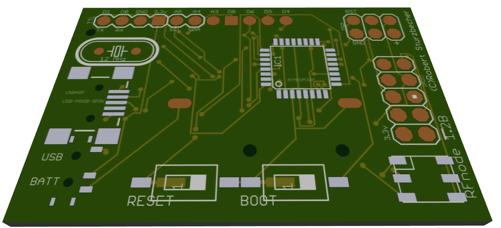
RFnode 1.2b PCB update


RFnode PCB version 1.2b almost ready for printing and have made many changes with this version (and a few more to come).

Major changes so far:


  • Added SDcard slot for storage on the under side. This will allow the RFnode to be used as a data logger. The problem with SDcard slot is that takes up a large chunk of PCB space and the SDcard libraries take up a lot of programming space so if using a Atmega168 you need to keep a close eye on your program size.
  • Replace Red&Green LEDs with a RGB LED. This opens up the full spectrum of colors. This also means I loose 3 analog I/Os but gain 2 digital I/Os. This leaves me with -3 Analog I/Os (includes 2 for i2c bus)
    -6 Digital I/Os (Includes 2 for serial and 1 for SDcard if used)
  • Breadboard friendly pin header. Now all of the I/Os are on a single 11pin breadboard friendly header. The boards were going to be just for another project I am working but have decided to open it up a little. So that means making the board more general purpose and Arduino hacker friendly.  
  • Better power consumption. I ended up caving in and adding a switch to select power source. It seemed to be the most simplest and cost effective solution to the power consumption issue I was having with the power regulator.
  • Optional pull up resistor pads added for D6 & D8. Makes it easy to add 1wire digital sensors like the DHT11 & DHT22 temperature and humidity sensors.    

Future Changes:
The board still has room to grow so there are some more changes to come.


  • Size. The board has grown a little in this version while I sort out and move features around but is still only approximately 45mm X 35mm. Most of that space is due to connectors and a few parts.
  • Lithium ion support. Looking to add a charge and protection circuitry for Lithium ion battery packs. Looks like a MCP73831T could handle the charging of the battery but now need to source the cut off protection side of things to protect the battery voltage from dropping too low. The problem with this I am running into is cost. It is cheaper to but a phone battery that has this built in then it is to buy the circuit by it's self. Currently I do lithium ion battery protection via software were the software will check the battery voltage then if it is too low will go to sleep (but still consumes a little less then 0.1mAh) 
  • More I/Os. The Radio uses 6 digital I/Os and the RGB LED uses 3 analog I/Os. Then if Using SDcard, serial and i2c bus you only get left with about 4 I/Os so I want to add more I/Os. I know there are chips that allow using the i2c bus to give you an extra few I/Os but I am thinking about something a little more powerful then one of these guys. I am thinking about adding a whole second processor. If I add a second Atmega168/328 I could off load all of the sensor work to the second processor leaving the first processor to handle the communications (USB, Radio, SDcard, RGB LED) then the second processor to handle everything else with almost all of his I/Os (13 digital and 4 Analog).
  • More memory. One of the problems I ran into with creating a meshing protocol with the RFnode beside battery life was lack of memory, routing tables take a lot of space. I did come up with a few memory tricks like creating a u_int8[256] array using the index as the remote RFnode ID then the value being where to address the packet so the next node can follow the same process and pass it on. This allowed to have a routing table of less then 256 nodes in 256bytes of memory. With a Atmega168 this is still about 25% of ram of 50% of EEPROM space and does not leave much space for routing data like number of hops and route health but still possible.
    So to fix the memory issue I am thinking about adding a i2c based ram/flash chip. This will also allow data logging without using the SDcard. 

RFnodes v1.1

RFnode PCB v1.1a
This version of the PCB I move some of the pins around to makes the unit more compact. As the boards normally take 3-4 weeks from time of ordering to arriving I ordered these boards before I had received and tested the Version 1.0 PCBs so had many of the same issues  


Assembled board with DHT11 temperature/humidity sensor attached

AMS1117 power consumption work around.
As a workaround to the AMS1117 power consumption issue I tried adding a diode that helped but only helped by dropped by about 70% and introduced a new issue of voltage drop from the voltage regulator dropping the voltage from 3.3 volts to 2.6 volts. USB still works and the board operates fine but not a long term fix.


I am trying to keep the board as user simple as possible so did not want to add switches. I also want to keep the board cost low so didn't want start adding item that would raise the cost too much (p-channel mosfets


RFnodes v1.0

RFnode v1.0
Time for a second post. This time with pictures.

These little guys are the Version 1.0 RFnodes I was working on, These were the first version I designed so expected a few issues. It is all part of my self inflicted crash coarse into PCB design and SMD (surface mount). This board is a few weeks old now and I have moved on to better designs since. 

The good
  • They are Arduino based (Atmega328/168) 
  • V-USB bootloader (same as USnooBie) http://www.frank-zhao.com/usnoobie/index.php
  • Runs at 12Mhz @ 3.3volts with onboard voltage regulator (AMS1117 3.3)
  • USB or 3 volt coin cell powered (CR2032) 
  • The PCB is designed by me from the ground up (printed in china)
  • Compatible with the USnooBie (as I own a few of them too and over time have found them easier to work with then many Arduinos)
  • Supports V-USB http://www.obdev.at/products/vusb/index.html
  • Uses nRF24L01+ 2.4Ghz radio 
  • Mostly SMD parts (and all soldered by hand) 
  • Some parts not SMD so I could change the sides if I wanted
  • 4 digital IOs (2 used for serial)
  • 6 Analog IOs (2 used for I2C)
  • 2 LEDS (Red/Green) 
  • ISP Header (only used for loading bootloader or adding another SPI device)
  • Can consume <0.1mAh in sleepmode and about 0.5mAh idle (read below)
     
 The Bad
  • The Radio overhang. This was done on purpose for this version of the board so the antenna is free from interference from the main board. After a bit of testing I decided I did not need to position the radio in such a way. 
  • SMD pad sizes. As I am a little new to SMD parts and their required pad sizes on the PCB some of my pads where too small for the part. Well it was only one part, The main power capacitor which I ended up just soldering to the voltage regulator pins.
  • Silk screen. Not all of the silk screen was printed or was too small or mostly off the edge of the board after cutting.   
  • Power consumption. Board was consuming about 17.5mAh so a CR2032 would only last about 6 hours which is less then the maths that said I should be able to get up to about 5 months. Issue turned out to being the AMS1117 power regulator would still consume about 4mAh if power was connected to it's output. I thought it was only meant to consume power if connected to input only. I also found that the radio was consuming about 13.5mAh when idle in RX mode. So after disconnecting the voltage regulator and powering down the radio when not in use I can the power consumption to less then 0.3mAh and less then 0.1mAh when in sleep mode.     
My finger compared to it's size, all soldered by hand (mostly my off hand)